Bridges / Tanks
Tanks
Liquid retaining structures, such as circular pipes, tanks and pressure vessels are admirably suited for circular prestressing. The circumferential hoop compression induced in concrete by prestressing counterbalances the hoop tension developed due to the internal fluid pressure. A reinforced concrete pressure pipe requires a large amount of reinforcement to ensure low – tensile stress resulting in a crack – free structure. However, circular prestressing eliminates cracks and provides for an economical use of materials. In addition prestressing safeguards against shrinkage cracks in liquid retaining structure.
In circular prestressing, the member may be pre stressed by overlapping tendons within the ducts so as to minimize friction losses. An alternative method is to wrap the high tensile wire under tension around precast cylinder member.
Cylindrical tanks are by far the most commonly used types from structural and construction considerations. Some of the largest pre - stressed concrete tanks constructed are circular in shape. A cylindrical shape is well suited for circumferential wire wrapping, which constitutes the major prestressing operation in tanks. Square or Rectangular tanks, spanning either vertically or horizontally, are required for industrial use. Square tanks are advantageous for storage in congested urban and industrial sites where land space is a major constraint.
Multi – celled tanks have been constructed using interlocking polygons and circular shapes, especially for the storage of cement in silo construction. The hexagonal units are prestressed together to achieve monolithic action by transverse and / or vertical tendons. The main advantage of this shape is the considerable reduction in the thickness of concrete shell and the use of the same set of straight wires to produce circumferential and vertical prestress. Doubly curved shells have also been used to take advantage of the efficiency of the shell action of the concrete, combined with prestressing at the edges.
Bridges
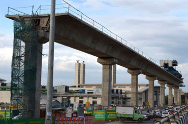
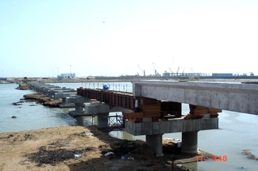
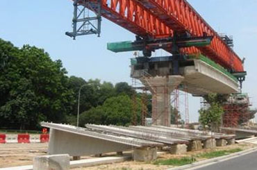
Prestress concrete is ideally suited for construction of medium and long span bridges. Solid slabs are used for the span range of (10 to 20m) , while T- Beam slab deck are suitable for span in the range of 20 to 40m. Single or muticell box girders are preferred for larger span of the order of 30 to 70m. Prestressed concrete is ideally suited for longer – span continuous bridges in which precast box girder of variable depth are used for span exceeding 50m. Prestressed concrete has been widely used throughout the world for simply – supported, continuous, balanced cantilever, suspension, hammer – head and bridle – chord type bridges in the span range of 20 to 500m.
Post tensioning bridge decks are generally adopted for longer span exceeding 20m. Bridge deck with precast post – tensioning girder of either T- type or Box – Type, in conjunction with a cast in situ slab are commonly adopted for spans exceeding 30m.
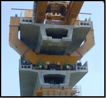
Post tensioning is ideally suited for prestressing long span girder at the site of construction, without the need of costly factory type installations like pre tensioning beds. Segmental construction is ideally suited for post tensioning work. In this method a number of segments can be prestressed resulting in an integrated structure.
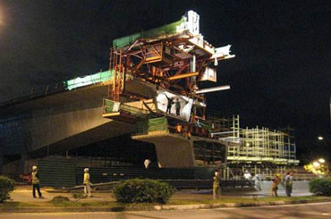
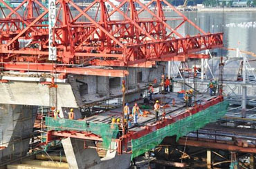
Segment
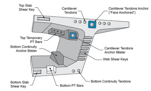
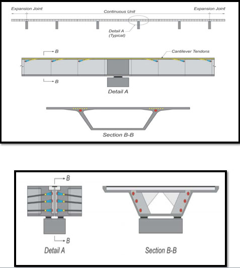
Above Figure presents a perspective of a typical balanced cantilever segment showing various features of the concrete shapes, post-tensioning tendon locations and post-tensioning anchorage locations. The principal types of post-tensioning tendons in these bridges are cantilever and continuity tendons. The cantilever tendons are stressed to resist the cantilever dead load moments during construction and the effects of superimposed dead loads and live loads on the continuous bridge. Continuity tendons are stressed to join adjacent cantilevers and resist positive moments from superimposed dead loads, creep redistribution, and live loads.
Longitudinal post-tensioning tendons for cantilever construction are contained within the top slab, usually spaced in a single layer over each web. For long spans, a second layer of tendons in the thickened haunch of the top slab may be required. The layout of the ducts is always the same at each side of the match-cast joint, and ducts shift sideways or up and down within a segment to make up the full tendon profile from an anchor at one end of the cantilever to that at the other. Relative to each segment, cantilever tendons always anchor in the same location. This may be in the end face of the segment or within an anchor block (or “blister”) on the interior of the segment. Cantilever tendons in the top slab of a box section counteract the bending effect from the self weight of the cantilever during construction. This bending induces a longitudinal tension stress in the top, reaching a maximum over the pier. The top cantilever post-tensioning counters these effects by inducing a compression stress of equal or greater magnitude at each cross section along the cantilever.
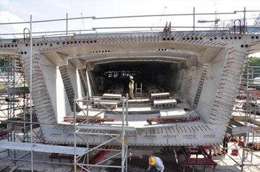
BOX GIRDER
A box girder bridge is a bridge in which the main beams comprise girders in the shape of a hollow box. The box girder normally comprises either prestressed concrete, structural steel, or a composite of steel and reinforced concrete. It is typically rectangular or trapezoidal in cross section. Box girder bridges are commonly used for highway flyovers and for modern elevated structures of light rail transport. The box girder can also be part of portal frame bridges, arch bridges, cable-stayed and suspension bridges of all kinds. Box girder decks are cast-in-place units that can be constructed to follow any desired alignment in plan, so that straight, skew and curved bridges of various shapes are common in the highway system. Because of high torsional resistance, a box girder structure is particularly suited to bridges with significant curvature.
Types of Box girder Bridges:
Based on Geometry:
* Simple monocellular box girders
* Monocellular box girders with ribs or struts
* Double-cell box girders
* Composite multiple box girders
Based on Material:
* Concrete Box Girder
* Steel Box Girder
* Composite Concrete Box Girder
ADVANTAGES:
* High stiffness against torsion compared to normal plate girders
* Good option when building bridges that curve in plane
* Smaller economical construction depth when compared to plate girders
* It has high structural efficiency and torsional strength which minimizes the prestessing force required to resist a given bending moment. Prestressing is not required for spans up to 60m.
* Their closed shape makes them more efficient in corrosion resistance than plate girders, as the shape drastically reduces the exposed surface area
* The upper flange can act also as a part of the deck structure
* Bracings can be hidden in the space available inside the girder and the structure becomes more aesthetic from outside.
DISADVANTAGES:
* One of the main disadvantages of box decks is that they are difficult to cast in-situ due to the inaccessibility of the bottom slab and the need to extract the internal shutter.
* Either the box has to be designed so that the entire cross section may be cast in one continuous pour, or the cross section has to be cast in stages.
* Box girders are more expensive to fabricate, and they are more difficult to maintain, because of the need for access to a confined space inside the box.
* Girders are not efficient as trusses in resisting loads over long spans.
* Typically higher construction costs compared to I-section steel girder
* Design part is complex
Box girder bridges are reasonable to use when:
* The spans range from 12 m to 300 m (Reference Barker and Puckett, Design of Highway Bridges)
* In girders curved in plan where there is higher torsion
* Fairly low depth is required
I - GIRDER:
A I -Girder Bridge, in general, is a bridge that utilizes girders as the means of supporting the deck. A bridge consists of three parts: the foundation (abutments and piers),the superstructure (girder, truss, or arch), and the deck. I girder bridge is very likely the most commonly built and utilized bridge in the world. Its basic design, in the most simplified form, can be compared to a log ranging from one side to the other across a river or creek.
A beam may be made of concrete or steel – many shorter bridges, especially in rural areas where they may be exposed to overtopping and corrosion, will utilize concrete box beams. The term “girder” is typically used to refer to a steel beam. In a beam or girder bridge, the beams themselves are the primary support for the deck, and are responsible for transferring the load down to the foundation. Material type, shape, and weight all affect how much weight a beam can hold. Due to the properties of inertia, the height of a girder is the most significant factor to affect its load capacity. Longer spans, more traffic, or wider spacing of the beams will all directly result in a deeper beam. In truss and arch-style bridges, the girders are still the main support for the deck, but the load is transferred through the truss or arch to the foundation. These designs allow bridges to span larger distances without requiring the depth of the beam to increase beyond what is practical – however, with the inclusion of a truss or arch the bridge is no longer a true girder bridge.
Few of our Projects
-
Chennai Metro Rail - Chennai
CLIENT: CMRL
CONTRACTOR: URC
STATUS: IN PROGRESS
Project Description:
* Supply and installation of Post – Tensioning component for the PT segment, box girder and I – girder bridges.
* Each type of bridge segment is fabricated and erected in different location.
* Each member has a span ranging from 25 – 40m
-
Karaikal –Nagore Bridge - Karaikal
-
BRADDELL INTERCHANGE- SINGAPORE
OWNER: Land Transport Authority
ENGINEER: TY Lin International Pvt Ltd
CONTRACTOR: Sato Kogyo Co. Ltd
UTRACON’S SCOPE: Segment Erection and Post-tensioning Works
YEAR OF COMPLETION: Feb 2008
Brief description:
* A total of 16 spans were constructed via precast segmental method.
* Each span consists of 11 to 13 pc of segments, with each segment measuring approximately 10.8m wide x 3.0m to 3.3m long.
* Typical bridge spans were 39m; the longest span was 75.6m.
* 172 pc of precast segments were erected using a combination of crane and winch, with segment weighing a maximum of approximately 55 ton.
-
Bayfront Bridge - Singapore
OWNER: Urban Redevelopment Authority
ARCHITECT: Cox Architecture + Architect 61
ENGINEER: Arup Singapore Pvt Ltd
CONTRACTOR: Sato Kogyo (S) Pvt Ltd
UTRACON’S SCOPE: Form traveler, PC Wing Slab Erection and Post-tensioning Works
YEAR OF COMPLETION: 2009
Brief description:
* Supply and installation of internal and external post-tensioning tendons to 300m long, 5 span bridge over Marina Reservoir.
* Supply and operation of form traveler to cast the 20m wide and 3m deep triple-cell box girder.
* Precast wing slabs are then installed on both sides of box girder to complete the 40m wide dual carriageway bridge.
-
NUS Campus Link Bridge - Singapore
OWNER: National University of Singapore
ENGINEER: TY Lin International Pvt Ltd
CONTRACTOR: Sato Kogyo Co. Ltd
UTRACON’S SCOPE: Segment Erection, Long Bed Casting Mould and Post-tensioning Works
YEAR OF COMPLETION: 2009
Brief description:
* The 100m main span of 280m long campus bridge was designed to span over the AYE expressway.
* All spans were cast-in situ, except for the main span which was constructed using precast segmental method.
* 29 pc of precast segments was erected using crane, with the segments weighing a maximum of approximately 90 ton.
-
Airport Road to Tampines Avenue - Singapore
OWNER: Land Transport Authority
ENGINEER: TY Lin International Pvt Ltd
CONTRACTOR: Sato Kogyo Co. Ltd
UTRACON’S SCOPE : PC Segment and Wing Slab Erection, and Post-tensioning Works
YEAR OF COMPLETION: Oct 2003
Brief description:
* The entire length of elevated viaduct (2.047km) was constructed using span by span precast segmental method.
* The 45m span dual carriageway viaduct is made up of a triple cell box girder measuring 2.6m deep x 11.24 wide and precast wing slabs (on both sides of the box girder) measuring 7.43m wide each.
* A total of 592pc of box girders and 1082pc of wing slabs were erected for the project.
-
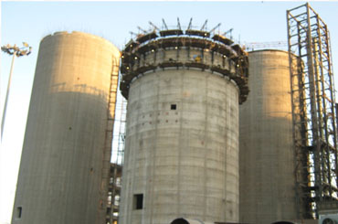
ABG Silo - Gujarat
-
Sewage Treatment Plant - Jurong, Singapore
Owner: Ministry of Environment, Singapore
Engineer: ST Architects and Engineers Pvt Ltd
Contractor: SembCorp Engineers & Constructors Pvt Ltd
Utracon scope : Tank Construction and Post-tensioning Works
Year of Completion: 2003
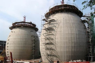
Brief description:
* Besides the 3 egg shaped digesters, the contract involved the construction of 8 final sedimentation tanks, 2 aeration tanks and 2 primary sedimentation tanks.
* Maximum storage capacity of each digester is 6,000m3each
* The digester’s diameter at equator is 20m and its overall height is 33m.
-
Tampines Newater Service Reservoir - Singapore
Owner: Public Utilities Board, Singapore
Engineer: KTP Consultants Pvt Ltd
Contractor: SembCorp Engineers & Constructors Pvt Ltd
Utracon scope : Tank Construction and Post-tensioning Works
Year of Completion: 2004
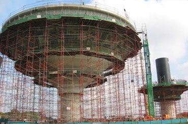
Brief description:
* 2 elevated cone shaped water tanks were constructed to store processed Newater from a nearby water treatment plant.
* Each tank measured 43.0m diameter at its mid height and it rose 31.5m above ground.
* The tank consists of a central access RC core measuring 5.9m in diameter, and was capped at its top with a steel roof.
* Each tank had a storage capacity of 8,448m3, and its tank wall measured 650mm at its base, tapering to a lean 480mm at its top.